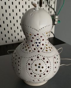
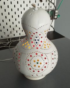
This year during our summer vacation we were in the Alanya area in the south of Turkey. One of the specialties in the area is the carving of pumpkins into lampshades. These are not the pumpkins you might know from Halloween, but rather the type also known as bottle gourds. They look a lot like huge peanuts.. at least to me.
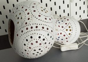 As you might expect, telling my 7 year old we would not buy one was naive and futile. Trying to ignore his pleas with watery eyes, just as much. So, we finally got one from a very friendly shopkeeper inside Alanya castle.
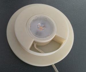
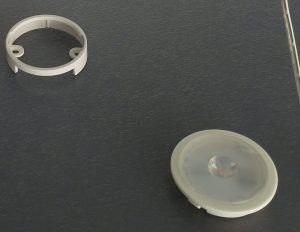 But what to do when you get home? Obviously not sticking a hot lamp inside, right? Nobody wants burnt little fingers and fires in a kids’ room. So I got a LEDBERG led spot from IKEA.
Now we had a small led spot sitting loosely on my sons desk and the lampshade even more loosely, on top of it. What a brilliant idea! — Hehe I know.
This needed a print, right? Somewhere I might have expected as much. 😉
First I gathered some measurements from the lamp:
- Diameter of the hole.
- Rough estimate of the depth of the weird dent underneath the pumpkin.
- Diameter of the IKEA lamp.
- The byte out of the lamp mount.
- Its screw holes’ location.
- Height and width of the cable connector.
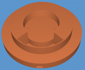 Then over to designing a lamp base in OpenSCAD. I will not show the first design iteration out of sheer embarrassment. It was completely overdesigned and way too complex. Only half an hour into the actual print did I realise that the LEDBERG had a detachable cable and was mountable with screws! Duh!
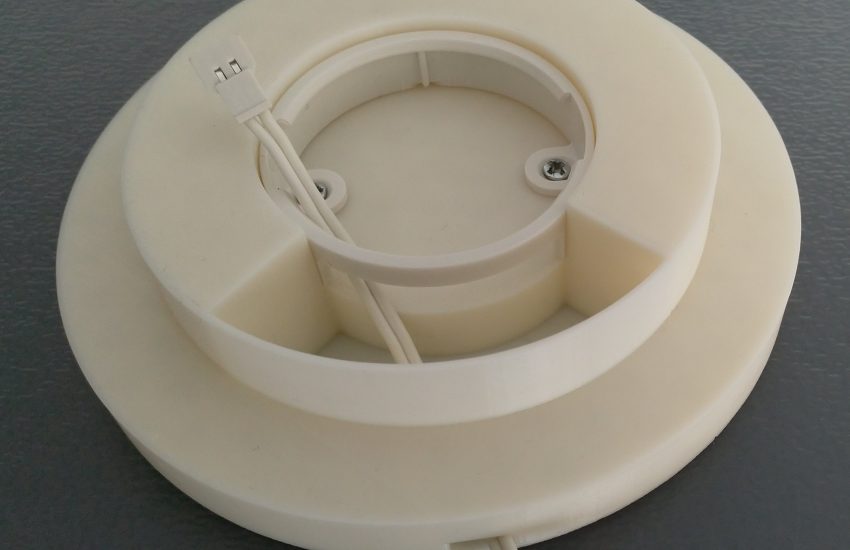
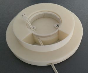
I chose to make a channel for the cable and a cavity hidden by the lamp shade itself so I could easily manoeuvre the connector.
For the screws, I found two screws I seemed to have salvaged long ago from some plastic device I trashed, be it accidentally or on purpose. All that was left, was to print it and see if everything fit.
- Always analyse the parts you want to integrate into your print. Remember that first print? Yeah!
- Inside the cavity, the cable starts all the way left where the connector is secured and runs to the middle. If I were to make a new one, I would place the cable channel to the left so that there is less tension and it follows a more natural path from where it is secured.